To help wholesalers support contractors in the field, Denny Martin, technical support engineer at Embraco, has compiled a resource manual to address the need for Embraco aftermarket product line information. Wholesalers use the manual to support contractors in the field—especially those who like to answer their own questions without having to call someone for assistance, or like to have a physical reference manual instead of looking online. The manual contains aftermarket cross references, part references and spec sheets for Embraco products. It has helped build awareness of Embraco among wholesalers and local technicians in the United States.
Martin worked shoulder to shoulder with contractors for ten years and learned quite a bit before becoming a counter salesperson with one of the biggest wholesalers in the U.S. Like a barber or bartender, he learned a tremendous amount by listening and talking to technicians in this capacity. This actually helped him learn what was going on with those tough service calls that may have required the dreaded “call back.” As industry technicians know, call backs can be a big problem.
Good training for the technicians is very important, but they also should be supported in the field when they have trouble. Martin has seen a knowledge gap with some of the newer techs and likes the idea of a senior technician working with a tech on a call-back job to ensure they know the reason for the call back, otherwise they may never learn what caused the issue. Call backs hurt the image of the entire refrigeration industry. With knowledge sharing and technician support, call backs could be kept to a minimum.
Top five best practices when changing a compressor in the field
Using his years of experience, Martin had identified the following five best practices when changing a compressor. Of course, safety in all procedures should be top of mind as the number one best practice when working in the field:
Gather information then check the entire system
Service calls should always begin with a conversation with the equipment owner to get as much information as possible about the failure.
– Was the system performing great right up to the failure or were there issues leading up to it?
– What’s the history? Has the system done well since installation and then a few years later had issues? This could indicate a lack of maintenance possibly in the form of a clogged condenser coil.
– Has the system had issues from day one? Maybe the installation or application caused the issues?
– What was the intended purpose of the machine and is it being applied in this manner?
– Does the unit have a dedicated electrical circuit and if not, has any equipment been added to that circuit?
– Asking a series of questions of the equipment owner is an easy way to start pin pointing problems. Denny says that in his service experience, this conversation usually indicated what the issue could be and where to look first.
Once you have some information, start with a visual inspection of the system, take note of any potential safety issues or poor equipment location without good ventilation. Check for loose or exposed electrical connections and make sure the unit is properly grounded. This is extremely important when you consider typical wet conditions and electricity in the field environment. Check the condition of the condenser coil, evaporator, and fans. If the unit will run, start it and check line voltage and observe any voltage drop at start up. Typical 115 volt compressors will have starting issues with voltage drops of 10% or around 103 volts. Take amp draw, system pressures, and verify good airflow through the coils. If you are not sure about the coils, use a piece of paper or small rag and see if the airflow will hold it against the coil and if practical, go ahead and clean the coils. These simple practices typically will reveal 90% of system problems.
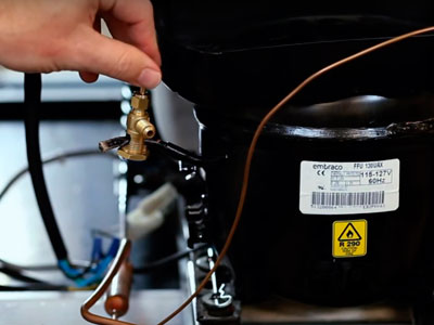
If a compressor is suspected to be bad, double check that the power is disconnected and inspect the start components and terminal connections for signs of arcing or corrosion. Sometimes the relay may smell burned from arcing. While this does indicate a failing or worn relay, it could also mean the compressor is starting under high current from high discharge pressure from a restricted or dirty condenser coil. Measure resistance through the windings and compare to the manufacturers spec sheet for that model. Readings should be within +/- 8% at 70 degrees F. Out of spec readings, open windings, or a compressor that is running with no pressure differential between the high and low side indicate a compressor failure. A compressor that is shorted to ground and tripping the breaker is easy to find, but using a Megohmmeter to test the condition of the motor insulation on a compressor that seems to run fine could prevent a future ground fault failure and save your customer the hassle of unit down time and system contamination from a burn out. When choosing a replacement, if the exact model is not available be sure the new model is within 10% capacity of the original and be prepared to adjust the factory charge listed on the unit name plate.
Keep it clean and dry
During compressor change outs or any time the system is opened for service, always keep copper tubing clean and dry by replacing caps on tubing rolls. Always deburr the tube after cuts preferably with a deburring tool and not a pocket knife. Take care to make cuts where copper shavings will not fall down inside the tubing. Use a shop vac when it does get inside the system. Debris in the system could end up in the cap tube or compressor bearings if not caught by the drier. Remember to limit the time the system is exposed to the atmosphere, don’t pull the compressor tube plugs until you are ready to fit it into the system. Observe a maximum exposure time of less than 15 minutes due to the refrigeration oils hygroscopicity or tendency to pull moisture out of the air. This moisture cannot be practically removed from the oil in the field. Technicians usually don’t pour out and measure the oil in the old compressor and compare it to the spec sheet but a difference of 2% less may indicate the need to flush the system to remove old oil. This oil stuck in the system will eventually return to the compressor possibly causing a repeat failure in a short time. A best practice while brazing is to bleed nitrogen at about 2-3 PSI through the system to displace any oxygen and prevent oxides or ash flakes inside the tubing. Modern refrigeration oils will act like a solvent and scrub this contaminant off the tube where it can become lodged in small orifices in the system. Since normal tank regulator valves are not practical for this purpose, special nitrogen regulators are available.
Perform a leak check
An important part of the process after the compressor change out is the leak check. Martin has found it helpful to simply pressurize the system with nitrogen to about 75-100 PSIG and go over all the joints with micro leak bubble solution, then leave pressure in the system for as long as possible and check for pressure loss. After 30 minutes, if there is less than one-half PSIG, you’ll know the system is tight. A trace amount of refrigerant with the nitrogen could also be used with an electronic leak detector as well. Some technicians like to use an electronic micron gauge during the evacuation process to check for leaks by monitoring for a rise in vacuum. Once 500 microns or less has been achieved, the manifold is valved off and any rise in vacuum indicates that either moisture is still in the system or there is a leak. The vacuum level should hold once the system is dry and tight. Technicians should use the method they are comfortable with without compromising effectiveness, which means verifying the vacuum level with that micron gauge. A leak often means required rework and customers are not always understanding when it comes to repeat issues with their equipment.
Remove all gases and moisture
One of the most important parts of the compressor change out process is the evacuation of all gases and non condensables out of the system. Non-condensables are any gas that will not condense under normal system pressures and they cause high discharge pressure because these gases take up space in the condenser coil effectively reducing its size and – capacity. This high pressure will put stress on the compressor causing it to be overworked. If that happens, the system may actually be unable to maintain temperature. The only course of action is to reclaim and weigh in a fresh refrigerant charge. After releasing the Nitrogen, the system should be purged well, again with nitrogen. Nitrogen helps to absorb any excess moisture in the system and push non-condensable gases and contaminants out. Always change the oil in the vacuum pump before every job. This insures it will be capable of pulling the system down effectively as moisture laden oil reduces the pump’s ability to pull a deep vacuum. Depending on the system and your equipment, always use the largest hoses possible. Remove Schrader cores as they are restrictive and can seriously hinder the process. A very effective way to perform a vacuum is to delete the manifold from the process by using Schrader tool/vacuum valves and attach hoses directly between the tools and the pump. These tools have good flow and hooking them directly to the pump can dramatically reduce pull down time, making levels of well under 500 microns achievable. After pulling the system down the Schraders can be re-installed using these tools as they have valves that prevent opening the system. The manifold can be re-introduced to the process through these valves and a final vacuum can be performed through the manifold. The final system vacuum should be verified with the micron gauge fitted to the system as far away from the pump as possible to be sure the gauge is showing system vacuum and not pump vacuum. Again, verify the system is at 500 microns or less and held there for 30 minutes. This low pressure in the system will ensure moisture is vaporized and easily removed by the pump, fully dehydrating the system. Any residual moisture will be trapped and held by the new drier.
Deliver the correct charge
When the system has been verified leak free and dehydrated, the charge should be weighed in using the amount listed on the manufacturer’s data plate. If the model compressor used is different than the original, this charge serves as a starting point and superheat or subcooling should be used to verify the system is properly charged. Remember to use superheat for fixed orifice metering devices and subcooling for TXV equipped systems as expansion valves attempt to maintain correct superheat by throttling open or closed making it difficult to determine the correct charge. Superheat is used on fixed orifice systems like capillary tubes for two reasons. First, it ensures the system has enough refrigerant to evaporate at the right time enabling maximum cooling efficiency. Second, it confirms no liquid is returning to the compressor from a refrigerant overcharge. Not only can this liquid damage valves and bearings over time, but flooding the evaporator reduces the system’s ability to do its job. Superheat is simply a measurement of the heat added to the refrigerant after it has vaporized in the evaporator. Having too little superheat means the liquid is not vaporizing completely in the evaporator and excess liquid ends up vaporizing in the suction line closer to the compressor. Zero degrees of superheat on the suction line indicates liquid has returned to the compressor. An ice cold suction line does not indicate a properly charged system. Typical superheat for low temperature systems should be 6 – 8 degrees and 8 – 10 degrees for medium temperature systems.
Small refrigeration systems typically have critical charges so extreme care should be used to accurately deliver the correct charge. Hoses should be kept as short as possible and care taken not to disturb the manifold or scale during the charging process. When ready to charge, let the tank pressure equalize into the system. Be sure to charge the gas in liquid form if it’s a blended component refrigerant. The tank should indicate the right tank orientation for proper charging. If charging liquid, carefully throttle the charging valve on your manifold to ensure liquid is introduced slowly and has a chance to vaporize in the hose. After system start up, the remaining refrigerant can be throttled in. After the whole charge is measured through your scale, valve off your manifold and the remainder in the charging hose can be let into the system. Let the system pull down to normal temperature and verify proper superheat or subcooling. Check the amp draw on all motors and the compressor. Once proper operation has been verified on the system the process tube can be crimped and soldered. Schrader service valves are not recommended on small systems with critical charges.
Following these five steps will ensure a complete compressor change out and help eliminate the need for a call back. Once the system is back up and running, review with the customer the steps you took to correct the problem and offer suggestions to prevent the issue from happening again.
Denny has served as the Aftermarket Technical Support and Product Line Manager for the past seven years. His responsibilities include ensuring technical support and training on Embraco products for technicians, wholesalers, and internal staff, and he also manages the aftermarket product line offerings from Embraco for North America.
Previous to his work at Embraco, Denny spent six years in counter sales for a major U.S. wholesaler of HVAC parts and equipment. His work experience also includes an additional ten years as an HVACR service technician working in commercial air conditioning.

By Denny Martin, Technical Support Engineer at Embraco